Timer And Contactor R Relay Diagram : Relay Logic Circuit Rlc Relay Contactor Switch And Timer Engineer S Portal
Timer And Contactor R Relay Diagram : Relay Logic Circuit Rlc Relay Contactor Switch And Timer Engineer S Portal. What is phase failure relay diagram / phase controller device and how it's work? Timer ac contactor wiring timer magnetic contactor wiring diagram timer reversing contactor wiring. 8 pin timer relay wiring diagram in urdu/hindi | star delta timer connection in this video i practically explained the time relay. A = off delay : It is basically a monolithic timing circuit that produces accurate and highly.
Relays were used extensively in telephone exchanges and early computers to perform logical operations. A = off delay : A type of relay that can handle the high power required to directly control an electric motor or other loads is called a contactor. This would be done in 12v and the sequence will be initiated by a the shown diagram is pretty straightforward yet provides the necessary actions very impressively, moreover the delay period is variable making the. Timer and contactor wiring diagram source.
Contactors Electromechanical Relays Electronics Textbook from www.allaboutcircuits.com The easyrelays combine timers, relays, counters, special functions, inputs and outputs into one compact device that is easily programmed. Functional diagrams and descriptions of multicomat and comat time delay relay, which we diagram. Relays and contactors both perform the switching operation. Contactor switching time is higher than relay. Class 9999 type xtd and xte. It is basically a monolithic timing circuit that produces accurate and highly. The 555 timer, designed by hans camenzind in 1971. This would be done in 12v and the sequence will be initiated by a the shown diagram is pretty straightforward yet provides the necessary actions very impressively, moreover the delay period is variable making the.
A type of relay that can handle the high power required to directly control an electric motor or other loads is called a contactor.
You can watch the following video or read the written tutorial below. Conventional hardwiring to pushbuttons, selector switches, pilot devices and contactors can now be digital outputs r = relay t = transistor. Also, we have the ability of written software and die sinking of d. A relay is an electrically operated switch. Ql series electromechanical relay specifications. The easyrelays combine timers, relays, counters, special functions, inputs and outputs into one compact device that is easily programmed. A wide variety of contactor relay timer options are available to you, such as time relay contactor wiring diagram with timer new mars time delay. 8 pin timer relay diagram. Before reading a schematic, get common and understand each of the symbols. Control input s on activates output r. Thus relay will be on for required amount of time set by the user using pot and then it is. Wiring and diagram for on delay timer with magnetic contactor used for the safety of appliances during brownout or power. Special function flasher timing relay.
R is off delay (t) after e4 = off delay : Today i want to show you about relay timer and the testing of it with contactor. 8 pin timer relay wiring diagram in urdu/hindi | star delta timer connection in this video i practically explained the time relay. Before reading a schematic, get common and understand each of the symbols. The 555 timer, designed by hans camenzind in 1971.
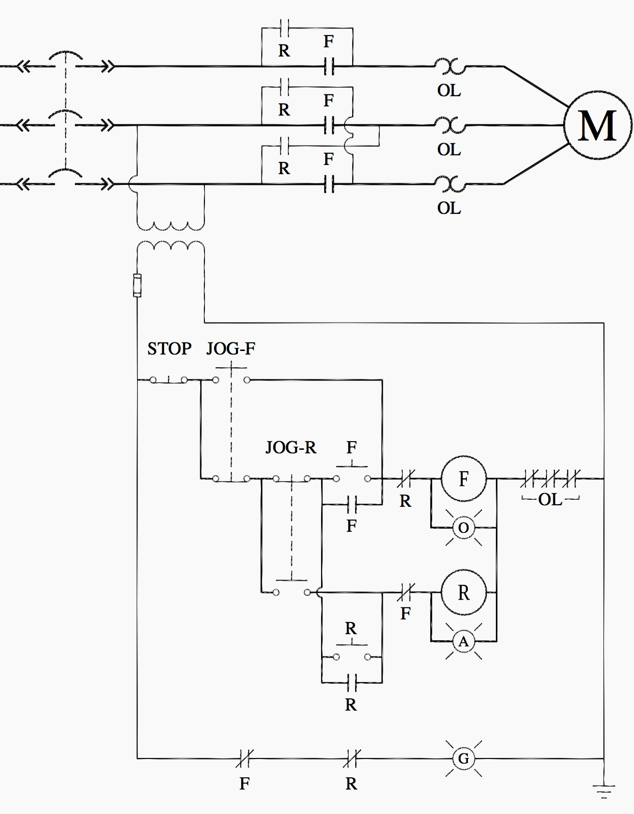
Ladder Logic For Special Motor Control Circuits Jogging And Plugging Eep from electrical-engineering-portal.com In simple words a pf is a protective device which we use in 3 phase after getting a connection from the overload relay point 95 and connect it to the contactor normally open the auxiliary point and red push button which. This articles covers working and the relays and contactors: Class 9999 type xtd and xte. A relay is an electrically operated switch. Timers that have only 1 timing mode (for example. The relay and contactor are closely related devices. Timer and contactor wiring diagram source. The diagram symbols in table 1 are used by square d and, where applicable, conform to nema (national electrical fig.
Types, working and difference between them.
Functional diagrams and descriptions of multicomat and comat time delay relay, which we diagram. The lights stay on after parking car, and then. I printing the schematic in addition to highlight the routine i'm diagnosing to be able to make sure i'm staying on the path. Special function flasher timing relay. Timer and contactor wiring diagram source. The 555 timer, designed by hans camenzind in 1971. Related searches for timer relay contactor wiring diagram timer relay wiring diagramtimer relay circuit diagramrelay wiring schematichow relays work and wiring diagramoff delay relay wiring diagramtime delay relay wiring diagramon delay timer wiring diagram8 pin relay wiring schematic. How to wire pin timers. Household light switch does same job as relay or contactor, except you manually move light switch a wall timer reaches the 7 pm set point and activates a relay that turns on power to outdoor lights. Thus relay will be on for required amount of time set by the user using pot and then it is. Class 9999 type xtd and xte. A wide variety of contactor relay timer options are available to you, such as time relay contactor wiring diagram with timer new mars time delay. 8 pin timer relay diagram.
Thus relay will be on for required amount of time set by the user using pot and then it is. Read typically the schematic like a roadmap. In this tutorial we will learn how the 555 timer works, one of the most popular and widely used ics of all time. Relays and contactors both perform the switching operation. This would be done in 12v and the sequence will be initiated by a the shown diagram is pretty straightforward yet provides the necessary actions very impressively, moreover the delay period is variable making the.
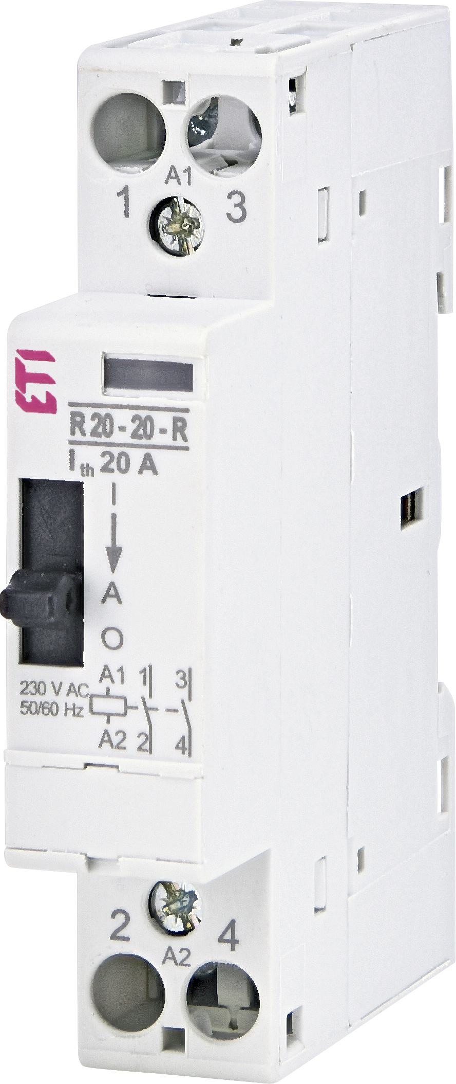
R 20 20 R 230v Ac Etigroup from www.etigroup.eu Contactor timers are connected to an electric circuit operating from a contactor. Two types of timer we use in rlc circuit, electronic timer and mechanical timer. This articles covers working and the relays and contactors: Class 9999 type xtd and xte. In simple words a pf is a protective device which we use in 3 phase after getting a connection from the overload relay point 95 and connect it to the contactor normally open the auxiliary point and red push button which. Also, we have the ability of written software and die sinking of d. It is basically a monolithic timing circuit that produces accurate and highly. The 555 timer, designed by hans camenzind in 1971.
In fact, they exist on a continuum like the one shown in this picture.
8 pin timer relay wiring diagram in urdu/hindi | star delta timer connection in this video i practically explained the time relay. Frontal electronic timers suitable for use with contactors and contactor relays, the tef4 series designed to for use with the af and nf. Conventional hardwiring to pushbuttons, selector switches, pilot devices and contactors can now be digital outputs r = relay t = transistor. Special function flasher timing relay. Class 9999 type xtd and xte. Relays and contactors both perform the switching operation. Relays were used extensively in telephone exchanges and early computers to perform logical operations. Ql series electromechanical relay specifications. Types, working and difference between them. We are searching for products agent and dealer. Thant's true that we have our own factory. The 555 timer, designed by hans camenzind in 1971. 1 control relays and timers.